LiDAR Accuracy Standards: What Industry Tests Prove

LiDAR accuracy is the life-blood of reliable spatial data acquisition. The basic concept shows how close a LiDAR measurement comes to the actual real-life value. At the time professionals discuss LiDAR accuracy, they express it as a range (±2cm) or as a standard deviation (3cm to 1σ).
The LiDAR domain has two main accuracy classifications: relative and absolute accuracy. Relative accuracy shows the precision of measurements compared to each other within the same dataset. It answers the question “How accurate are the measurements relative to each other?”. This internal precision sets confidence levels when comparing points within a point cloud, whatever their exact position on Earth. Absolute accuracy measures how the LiDAR data matches true geographic locations on Earth’s surface. It answers a simple question: “How close are my measurements to the true values?”.
Statistical comparison between known (surveyed) points and measured laser points determines LiDAR accuracy. Standard deviation and root mean square error (RMSE) serve as common statistical measures in the industry. The difference between ground control points and LiDAR elevations helps assess vertical accuracy, which typically ranges between 5 and 30 centimeters.
These factors affect LiDAR accuracy:
- Hardware components – each with their own accuracy values expressed as either distance or angle
- Systematic errors from miscalibration or compass bias
- Random errors/noise in measurements
- Environmental conditions affecting signal quality
- Processing algorithms and filtering methods
A simplified formula calculates the overall accuracy for a LiDAR system:
Overall accuracy = √[(GNSS error)² + (LiDAR range error)² + (range * tan(INS error))² + (range * tan(LiDAR – INS error))²]
The accuracy decreases as distance from the sensor increases due to the INS’s angular error. This makes it significant to understand the range where a stated accuracy figure came from. Users can get vertical accuracies better than 15 cm at 1,200 m of altitude in optimal conditions.
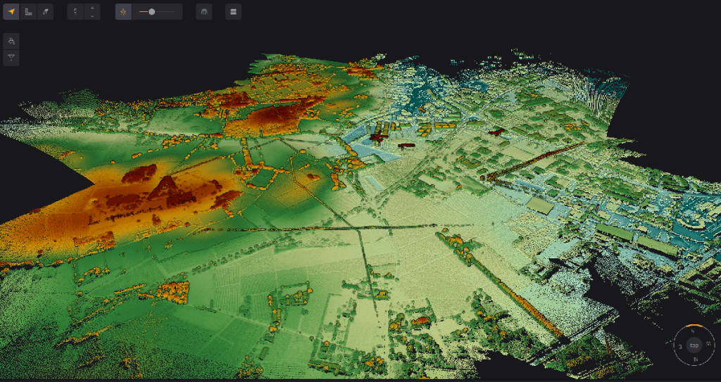
Point cloud generated in YellowScan CloudStation
Industry-Recognized LiDAR Accuracy Standards
Standards that are 10 years old form the foundation to ensure LiDAR accuracy in industries of all types. These frameworks give consistent methods to measure, report and prove spatial data quality right.
ASPRS accuracy classification system
The American Society for Photogrammetry and Remote Sensing (ASPRS) provides the most complete and accessible standards to assess LiDAR accuracy. The ASPRS Positional Accuracy Standards for Digital Geospatial Data, Edition 2 received approval in August 2023. This edition updates the first version from 2014 that led the way in digital mapping guidelines.
The revised standard brings several key improvements:
- No more 95% confidence level references as accuracy measures
- Target accuracy requirements for ground control points now need twice the accuracy instead of four times
- The minimum checkpoints increased from 20 to 30 for accuracy assessment
Edition 2 now expresses horizontal accuracy as RMSEH (combined linear error in the radial direction) rather than separate RMSEx and RMSEy values. The standard requires specific checkpoint distributions with at least 30 checkpoints spread evenly across project areas.
ISO standards for geospatial data accuracy
The International Organization for Standardization (ISO) handles LiDAR accuracy through its ISO/TS 19159 series. ISO/TS 19159-2 specifically covers “the data capture method, relationships between coordinate reference systems and their parameters, as well as calibration of airborne LiDAR sensors”. This technical guide standardizes calibration processes geometrically, radiometrically, and characteristically for applications in a variety of areas like land, ice, forest, water, and atmosphere.
Federal Geographic Data Committee (FGDC) standards
The FGDC created the National Standard for Spatial Data Accuracy (NSSDA). This standard uses root-mean-square error (RMSE) to estimate positional accuracy of geospatial data. Testing requires an independent source with higher accuracy and at least 20 check points distributed across the geographic area.
The Geospatial Data Act of 2018 made FGDC the lead organization to develop geospatial data standards. Federal agencies must comply with these standards when they collect or produce geospatial data. Non-federal agencies get encouragement to adopt these standards to make data sharing easier.

Digital geospatial data based on Earth’s position
How LiDAR Accuracy Is Tested and Verified
LiDAR systems need rigorous testing methods that prove it right for both relative and absolute accuracy measurements. A full picture will give you the confidence that collected data meets project specifications and industry standards before use in critical applications.
Ground control point verification methods
Ground Control Points (GCPs) work as reference markers with known coordinates to prove LiDAR data accuracy. These points work as tie points in processing software. They tell the point cloud about scale, orientation, and help improve overall data quality. GCPs should sit on flat or uniformly-sloped open terrain with slopes of 10% or less to work. You should avoid vertical artifacts or sudden elevation changes.
Real-Time Kinematic (RTK) surveying offers the quickest way to collect GCPs. This technique needs two GNSS receivers: a static reference station (base) and a mobile receiver (rover). The base sends correction data to the rover and gives centimeter-level accuracy—usually 1-3 cm—when setting up GCP locations.
Surveyors must tell apart two types of control points: Ground Control Points (GCPs) for data adjustments and Survey Checkpoints (SCPs) just for accuracy reporting. Checkpoints never change how the survey gets processed, which helps them stay independent for validation.
Relative accuracy assessment techniques
Relative accuracy, also called “swath-to-swath accuracy” or “interswath consistency,” shows how well overlapping areas of data collection match each other. This internal geometric quality check looks mainly at vertical differences between overlapping flight paths.
The assessment process uses several methods:
- Surface-based comparison: Ground surfaces come from point-to-digital (PTD) algorithms at the per-flightline level. Each surface gets compared to ground-classified points from all overlapping flightlines. The differences get recorded and summarized.
- Statistical analysis: You need to check overlap consistency at multiple spots within non-vegetated areas. These areas should have only single returns and slopes less than 10 degrees. A polygon shapefile shows the interswath consistency through sample areas. The file includes attributes like minimum difference, maximum difference, and RMSDz values.
Absolute accuracy measurement protocols
Absolute accuracy testing matches LiDAR measurements against independently surveyed points of higher accuracy. The team compares elevations from the LiDAR dataset with elevations from checkpoints at similar x/y coordinates for vertical accuracy assessment.
ASPRS standards say accuracy testing needs at least 20 checkpoints, though the latest standards suggest 30. Areas smaller than 500 square kilometers need at least 20 Non-vegetated Vertical Accuracy (NVA) and 5 Vegetated Vertical Accuracy (VVA) checkpoints.
Horizontal accuracy assessment compares planimetric coordinates of well-defined points with coordinates from higher-accuracy sources. Notwithstanding that, surveyed control points don’t work well for estimating absolute horizontal accuracy in LiDAR-derived elevation data. The point cloud data’s sparse nature compared to high-resolution imagery causes this limitation.
Cross-validation with alternative measurement systems
Testing LiDAR data against other measurement technologies builds extra confidence in accuracy assessments. Total stations lead the way in validation because they offer better precision than GPS methods. GPS accuracy depends on base point distances, observation time, and satellite geometry.
Software like CloudCompare helps compare point clouds from different methods. One study looked at GPCs from USGS LiDAR versus total station measurements. The results showed average 2D (X,Y) differences of 2.2 inches and average 3D (X,Y,Z) differences of 5.9 inches.
Cross-validation with photogrammetry works by processing the same imagery with different GCP sources. The process lines up using equivalent point pair tools and adjusts only translation and yaw parameters to check elevation differences. This method helps verify accuracy without needing lots of field equipment or site visits.
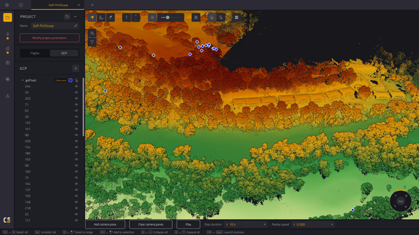
Cloudstation GCP parameters
Key Factors Affecting LiDAR Scanner Accuracy
LiDAR systems’ precision depends on complex interactions between multiple technical and environmental variables. Practitioners need to understand these influences to achieve better accuracy in real-life conditions.
Hardware specifications and limitations
Sensor components quality affects measurement precision. High-end LiDAR sensors deliver better accuracy than lower-quality ones. The system needs proper calibration to achieve reliable data. Small calibration errors can spread throughout the point cloud and reduce overall accuracy.
Inaccurate GNSS and IMU data directly affect the final point cloud’s georeferencing. The flying attitude (roll, pitch, and heading) of airborne systems creates errors when sensors rotate unexpectedly during collection. Flying height doesn’t affect accuracy directly, but it changes point density, which affects precision in complex terrains.
Environmental and atmospheric conditions
Weather creates major challenges for LiDAR operations. Laser signals scatter or get absorbed by rain, fog, and dust particles, which leads to poor measurements. Range measurements stay stable even during heavy rainfall, with changes usually below 20 centimeters. Rain reduces both return intensity and detected points, especially on pavement surfaces.
Changes in air density due to humidity affect sensor calibration. Extreme temperatures change both drone operation and sensor performance. Systems face problems from direct sunlight due to its intensity and wavelength overlap.
Data processing algorithms and filtering
Advanced filtering algorithms enhance accuracy by cleaning raw point clouds of noise, outliers, and unwanted points. Data refinement uses different approaches like Voxel Grid Filters, Statistical Outlier Removal, and Radius Outlier Removal.
Areas with varied elevations make ground filtering difficult because algorithms can’t easily tell ground points from non-ground points. Simple noise filtering methods don’t separate static background elements from dynamic objects well. Kalman Filters and machine learning approaches help improve classification accuracy to solve these problems.
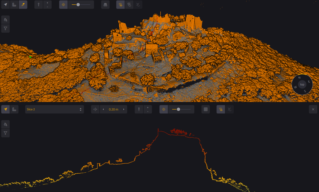
Slice of Montferrand Castle in YellowScan CloudStation software
Common LiDAR Accuracy Problems and Solutions
LiDAR deployments work best when teams recognize and fix specific accuracy challenges that can affect data quality. Technology has advanced, but some basic limitations still exist. Teams must address these through careful calibration and processing techniques.
Systematic errors and calibration issues
Systematic errors pose a major challenge in LiDAR systems. These predictable measurement deviations hurt accuracy. The errors show up mainly through boresight misalignment—the angular offset between the LiDAR sensor and the onboard GPS/INS coordinate system. This misalignment creates the biggest systematic error in UAV-LiDAR operations. Flight altitude and scan angle make its effects even worse.
Miscalibration affects point cloud reconstruction in two key ways in aerial systems. Boresight errors create gaps between overlapping flight lines, which leads to inconsistent elevation values for similar ground locations. These errors also create distortions that grow larger as distance from the sensor increases.
Teams use two main approaches for effective calibration:
- Intrinsic calibration works on internal parameters of the LiDAR sensor, including laser beam alignment, using calibration targets with known dimensions.
- Extrinsic calibration matches the LiDAR with other sensors like cameras or radar to ensure accurate data fusion.
Studies show that proper calibration techniques can reduce reprojection, rotation, and distance errors by a lot. Yes, it is common for specialists to use strip alignment software. This helps fix leftover systematic errors by adjusting position and angles throughout the mission.
Random errors and noise reduction strategies
Random errors differ from systematic ones. They come from unpredictable fluctuations in measurement processes. The main sources include quantum noise (shot noise) from light’s discrete nature, thermal noise from random electron motion, and excess noise from photomultiplier tubes during analog detection.
Point cloud noise reveals random errors. You can see this when looking at average slope values from full-resolution LiDAR. These values look unusually high even on flat ground. This happens because vertical accuracy (usually 12-15 centimeters) creates random height differences between nearby points of 24-30 centimeters. Points just 1 meter apart horizontally create what signal processing experts call “high frequency noise”.
Teams can reduce noise through:
- Statistical filtering to spot and remove outliers based on spatial distribution patterns
- Window-size filtering to boost the ratio of horizontal sample density to vertical accuracy
- NSF (noise scale factor) method to estimate random error without atmospheric variability effects
Accuracy degradation in challenging environments
Real-life conditions affect LiDAR performance through various environmental factors. Rain, fog, and dust scatter or absorb laser beams, which leads to incomplete or wrong data. Fog affects accuracy because of water particle scattering. Rain changes both signal intensity and point density.
Reflective surfaces create special challenges for LiDAR systems. Light beams get distorted by mirror-like objects and glass walls, making accurate distance measurement impossible. These distortions cause errors in simultaneous localization and mapping (SLAM). This increases accident risks in autonomous vehicle applications.
Specialists use several strategies to boost performance in tough conditions:
- Adaptive algorithms that adjust for environmental interference in real-time
- Multiple sensor fusion that combines LiDAR with cameras, radar, and GPS
- Advanced filtering techniques like Low-Intensity Outlier Removal (LIOR) and Dynamic Distance-Intensity Outlier Removal (DDIOR)
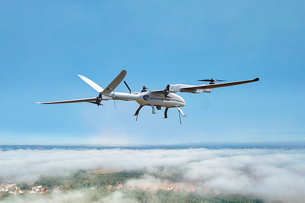
YellowScan LiDAR mounted on a fixed-wing drone, scanning above a sea of clouds.
The Future of LiDAR Accuracy Standards
LiDAR accuracy standards continue to progress with technological advancements and expanding applications. The American Society for Photogrammetry and Remote Sensing (ASPRS) has released their second edition of Positional Accuracy Standards for Digital Geospatial Data, which brings the most important changes to previous frameworks. These changes include renaming RMSE terms – RMSEz becomes RMSEV and RMSEx/RMSEy combines into RMSEH. The new standard no longer refers to 95% confidence level as an accuracy measure and has less strict requirements for ground control points.
State-of-the-art developments in technology have led to unprecedented improvements in accuracy. Coherent Doppler LiDAR systems now deliver measurement precisions better than 0.8 centimeters per second for velocity and 0.8 meters for range. The next generation of sensors will achieve centimeter-level accuracy at greater distances, which improves applications in surveying, construction, and autonomous navigation.
Solid-state LiDAR brings a fundamental change toward better reliability by eliminating moving parts. This advancement makes systems more durable and improves real-life 3D mapping capabilities. Several manufacturers have announced technologies that achieve 99.9% accuracy in object tracking and 98.9% in object recognition using LiDAR alone.
AI integration reshapes what LiDAR can achieve in terms of accuracy. AI-driven algorithms automate object recognition, improve point cloud filtering, and optimize up-to-the-minute decision-making. These improvements help systems handle challenging weather conditions like rain and fog better, with one solution doubling detectable distance from 20m to 40m in heavy rainfall.
Future standards will likely include multi-spectral LiDAR capabilities as these systems capture data across multiple wavelengths to classify materials better. High-accuracy systems are becoming available in a variety of industries thanks to miniaturization trends.
Future LiDAR systems’ accuracy will still depend on calibration parameters, point density, flight parameters, and data processing techniques. Research now focuses on improving range, resolution, real-time execution, power efficiency, and deeper AI integration.
Frequently Asked Questions
How is LiDAR accuracy typically assessed?
LiDAR accuracy is commonly evaluated using ground control points (GCPs) with known coordinates. Surveyors compare LiDAR measurements to these independently surveyed points, typically requiring a minimum of 20-30 checkpoints distributed across the project area. Statistical measures like root mean square error (RMSE) are used to quantify the accuracy.
What range accuracy can modern LiDAR systems achieve?
Modern LiDAR systems can achieve impressive range accuracy. High-end sensors can attain accuracies of 0.5 to 10mm relative to the sensor, with mapping accuracies of up to 1cm horizontally and 2cm vertically. Some advanced systems even approach centimeter-level accuracy at greater distances.
What are the industry-standard file formats for LiDAR data storage?
The LAS (LASer) and LAZ (compressed LAS) file formats are widely recognized as industry standards for storing and sharing LiDAR data. These vector formats efficiently store point cloud data and are compatible with numerous software tools, making them essential for interoperability in the surveying and mapping industries.
How do environmental factors affect LiDAR accuracy?
Environmental conditions significantly impact LiDAR performance. Factors such as rain, fog, dust, and extreme temperatures can scatter or absorb laser signals, degrading measurement accuracy. For instance, heavy rainfall can reduce the intensity of returns and the number of detected points, particularly when scanning surfaces like pavement.
What role does AI play in improving LiDAR accuracy?
Artificial Intelligence is increasingly enhancing LiDAR accuracy capabilities. AI-driven algorithms automate object recognition, improve point cloud filtering, and optimize real-time decision-making. These advancements allow systems to compensate for challenging environmental conditions, with some solutions doubling detectable distances in adverse weather like heavy rainfall.